If you have trouble viewing this, try the pdf of this post. You can download the code used to produce the figures in this post.
A projection simulator--Matlab implementation
edit: Sep 9, 2011 I extended the code to include convex polygons and renamed the function as CTProjSim .
I previously discussed the rationale, the C++ implmentation, and the the Matlab interface for a computed tomography projection simulator. In this post, I discuss a Matlab-only implementation of a simulator. The simulator is includes ellipses and convex polygons.The projection lines are assumed parallel but it is simple and can be (fairly) easily extended to other object types and geometries.
Ellipse
The geometry for the ellipses is shown in Fig. 1↓. With this geometry, the length of the intersection of the projection line with an ellipse is
T = ⎧⎨⎩
2ab√(s2m − s2) ⁄ s2m
|s| ≤ sm
0
|s| > sm
where s is the distance of the line L from the center of the ellipse and θ is the angle from the perpendicular of the line to the principal axis of the ellipse. Also, the maximum offset of the ellipse perpendicular to the projection line is s2m = a2cos2(θ) + b2sin2(θ).The code of the function CTProjSim is a straightforward implementation of these formulas.
I used the function to compute the projections of the Shepp-Logan phantom and reconstructed with my CTrecon function. The results are shown in Fig. 2↓.
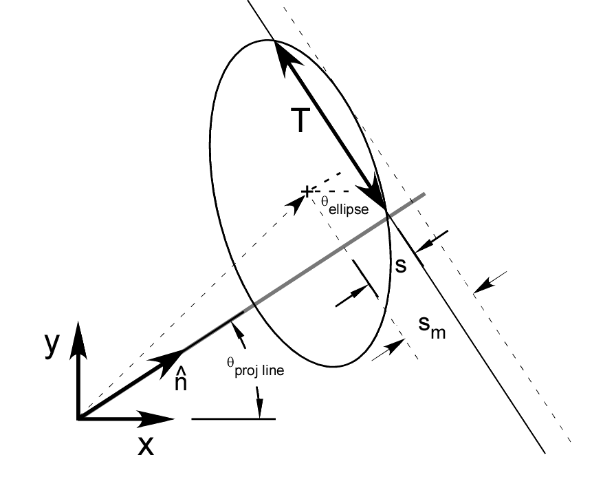
Figure 1 Geometry of simulator. The ellipse has major and minor semi-axes a and b and the major axis is at angle θellipse with the x-axis. The ellipse center is zell − centerand the perpendicular to the projection line is n̂. Therefore the offset of the center along the projection line perpendicular is ellipse_center_offset = n̂⋅zell − center.
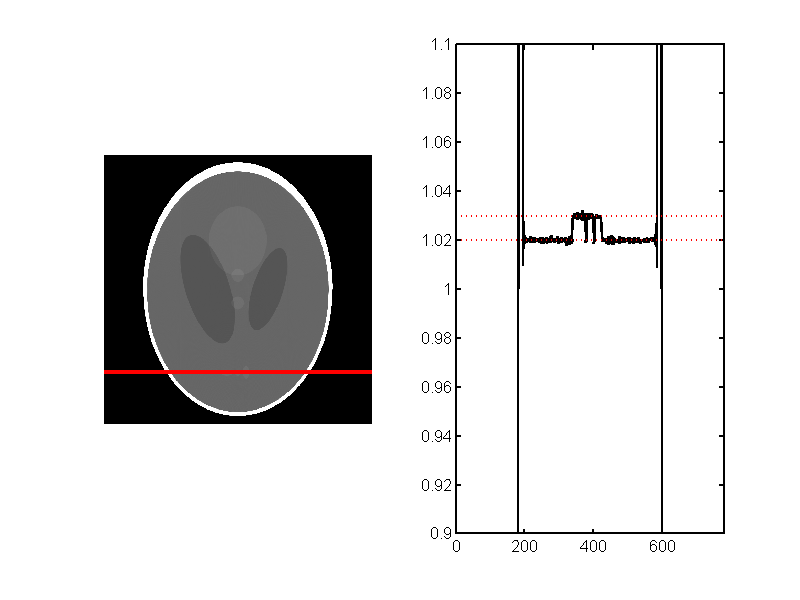
Figure 2 Reconstruction of projections of Shepp-Logan phantom produced with CTProjSim. My CTrecon function was used to reconstruct so the results do not have the offsets introduced by the Matlab iradon function. The red lines are the accurate values of the phantom density.
Convex polygon
We can use concepts from my previous posts on intersection of line segments and polylines to compute the intersection of a line with a polygon. I assume the polygon is convex so the line can intersect with at most two segments of the polygon. The geometry is shown in Fig. 3↓. In two dimensions, we can specify a line by a vector n through the origin and perpendicular to the line. We can write n as nn̂, where n̂ is a unit length vector. If the line passes through the origin, n = 0, but we still know its direction from n̂.
A point on the line is
rL = nn̂ + tŝ
while a point on the line segment is
rS = P1 + ud.
At the intersection,
rL = nn̂ + tŝ = rS = P1 + ud.
Taking the dot product of this equation with n̂
n = n̂⋅P1 + un̂⋅d
Solving for u
u = (n − n̂⋅P1)/(n̂⋅d)
To find the intersection of a line with a polygon, we can test 0 ≤ u < 1 for all the segments of the polygon sides. If there are two intersections, then the line overlaps the polygon. We can compute the intersect length T as
T = |rintersect, 1 − rintersect, 2|
Multiplying T by the (possibly vector) density gives the line integral.
These formulas are implemented in the CTProjSim along with the code for the intersection with ellipses. Line integrals are linear so we can add the line integrals for different shapes for each projection line.
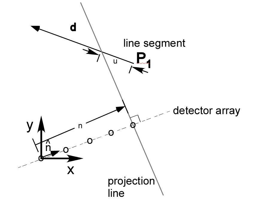
Figure 3 Intersection of a line and a line segment. The line is specified by a vector n through the origin and perpendicular to it. We can express n is nn̂, where n̂ is a unit length vector. The line segment is specified by an endpoint P1 and a vector d to the other endpoint. The intersection of the line with the extended line segment is at P1 + ud. The intersection is within the line segment if 0 ≤ u < 1 .
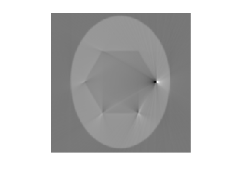
I created the projections of a hexagon embedded in an ellipse and reconstructed them to produce the image in Fig. 4↓. The sharp vertexes of the polygon cause large aliasing artifacts in the reconstruction. I reduced them somewhat by filtering them with the ’filter_type’, ’hamming’, ’freq_cutoff’, 0.9 parameters in CTrecon. You can download the code to reproduce the figures in this post.
Last edited Sep. 9, 2011
© 2011 by Aprend Technology and Robert E. Alvarez
Linking is allowed but reposting or mirroring is expressly forbidden.