If you have trouble viewing this, try the pdf of this post. You can download the code used to produce the figures in this post.
Beam hardening 3: reconstruction of nonlinear terms
The first post in the discussion of beam hardening derived a Taylor’s series for logarithm of the x-ray measurement L,
where x is the object thickness. Since line integrals are linear operators, the inverse operator, that is the image reconstruction operator ℛ, is also linear so that
where c1 and c2 are constants and P1 and P2 are sets of line integrals, which I will also refer to as projections. Letting c1 = (∂L)/(∂x)(0) and c2 = (∂2L)/(∂x2)(0) in the Taylor’s series in Eq. 1↑, the reconstruction of the logarithm of the x-ray measurement is
ℛ[L] = c1ℛ[x] + c2ℛ[x2].
The first term is the reconstruction of the projections, which is what we want, while the second term, the reconstruction of the squares of the projections, leads to artifacts. There are also be higher order terms but I will assume they are negligible although they can be analyzed similarly to the discussion here.
In this post, I will discuss some of the properties of the reconstruction of the nonlinear term and apply it to models of common beam hardening artifacts. This gives us some insight into the types of artifacts that we can expect from beam hardening.
Head in CT scanner with water bath—cupping artifact
In the first post of the beam hardening discussion, I showed that with a water bath the object reconstructed can be thought of as having an attenuation coefficient equal to the actual coefficient minus the attenuation coefficient of water. Assuming for the purposes of analyzing beam hardening that the attenuation coefficient of the brain is approximately equal to that of water, we can model the head as an empty cylinder (no pun intended) with attenuation coefficient equal to the coefficient of cortical bone minus water. For simplicity, the head is assumed to be circular with its center at the center of rotation of the scanner.
Fig. 1↓ shows the reconstructed images. A 120 kilovolt x-ray tube spectrum is used. From the discussion of a water bath, the spectrum was filtered by water with a thickness equal to the skull diameter plus one. The skull is assumed to be composed of cortical bone, obviously an approximation. For more details, see the the code for this post.
The top panel is the reconstruction of the logarithm of the measurements L. Superimposed on the image is a plot of the data on a line through the center of the head. The line is shown in green and the plotted data are in yellow. The panel on the right re-plots the image data. Notice the “cupping” artifact near the skull. Also notice that there is also an artifact inside the skull.
The center panel shows the reconstruction of the linear term in Eq. 1↑. The image data shows that this is the rectangular cross section of the skull cylinder with some aliasing artifacts due to the sharp edges of the cylinder.
The bottom panel shows the reconstruction of the squared term. The nonlinearity causes “cupping” artifacts inside the skull and the interior of the head.
(a)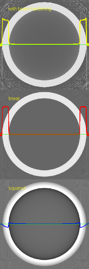 (b)
(b)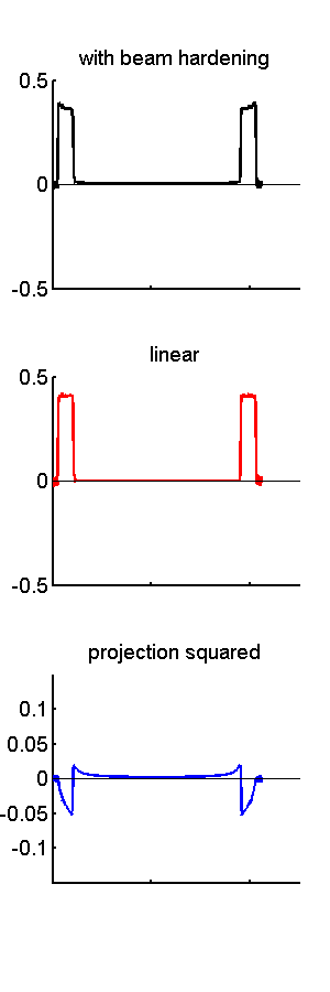
(b)
Figure 1 Reconstructed images of a model of a CT image of the head with beam hardening. The images (a) are on the left and plots data on line through center are (b) on the right. The images are: the single energy approximation with beam hardening (top), the linear term (middle) and the squared term (bottom). The image data on the green through the center of the images is also plotted on the images and in the panel on the right. Note that the image with beam hardening is approximately the sum of the linear image and the squared image.
Petrous bone artifact
The petrous (rock-like) ridges are two protuberances (outcroppings) of the skull near the base of the brain. They are extremely dense and can cause beam hardening and other nonlinear artifacts between them. The artifacts are a serious problem because they interfere with visualization of the brain stem. They are also interesting because they are an example of nonlinear artifacts that extend outside the original object.
We can use the Taylor’s series approach to study the petrous artifact by modeling the ridges as two cylinders of cortical bone. Fig. 2↓ shows images and plots of data for two cylinders composed of cortical bone. There are several interesting features of the artifact image in the bottom panels. The first is that there are artifacts both inside the object but also outside, mostly between the cylinders but some extending outside of them. The artifacts inside the cylinders are not symmetrical but cup towards the inside. The artifact between the cylinders is not circularly isotropic but it forms an “X” shape. Finally notice that there are four bright artifacts and horizontal lines tangential to the outside the cylinders. The nonlinearity can cause streak artifacts outside the object. These streak artifacts are also observed if there are metal objects such as dental fillings or hip implants inside the body.
(a)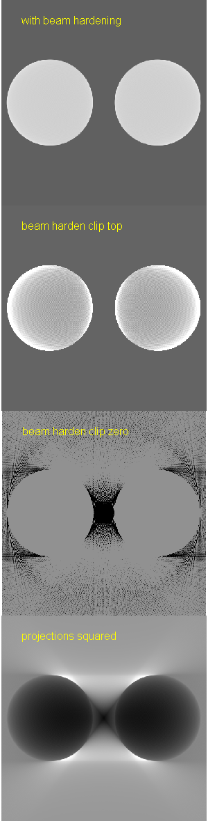 (b)
(b) 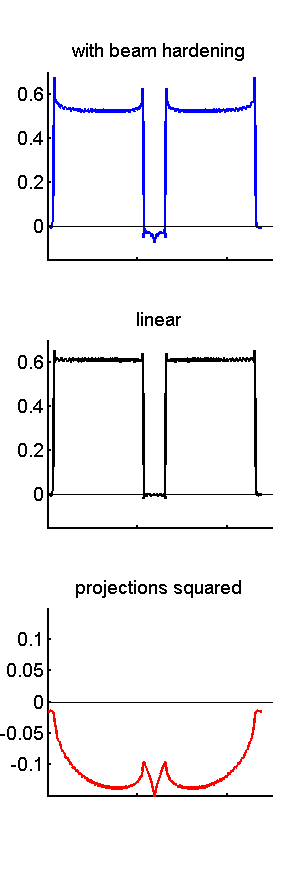
(b)
Figure 2 Images and data of two bone cylinders with beam hardening. This is a model of the petrous ridge artifact, which is a problem with images of the brain stem. The images are on the left and plots of the data on a horizontal line through the center are on the right. Views of the beam hardening image with different gray level windows are shown to display the artifact in different parts of the object.
Discussion
The Taylor’s series model gives us a good tool to study the behavior not only of beam hardening but also other nonlinearities in computed tomography. Nonlinearities abound in x-ray CT because many seemingly innocuous effects such as scatter and finite width x-ray beams can lead to artifacts because of the exponential followed by linear averaging and then logarithm signal processing used in CT scanners.
Last edited Jul 10, 2015
Copyright © 2015 by Robert E. Alvarez
Linking is allowed but reposting or mirroring is expressly forbidden.